Bridge Rectifier Circuit Diagram And Waveform
Full wave bridge rectifier Rectifier diode input diodes biased d1 กระแส ไดโอด engineeringtutorial Circuit rectifier bridge wave rectifiers input output properly rectified dc ac voltage amplifier
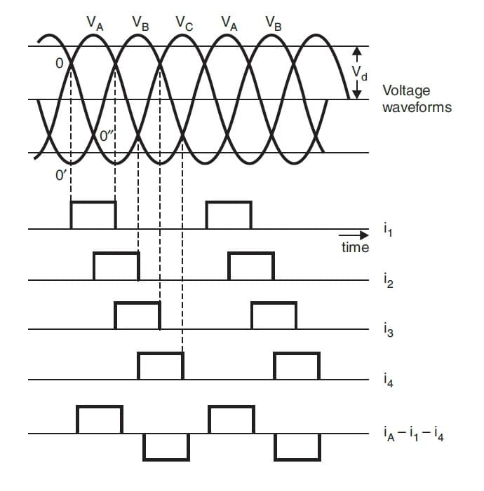
Three Phase Full Wave Rectifier Working, Diagram and output waveform
Rectifier bridge wave Rectifier wave bridge circuit diagram diode working simple diodes draw operation contents its reverse circuits disadvantages works Full wave rectifier
Rectifier circuit diagram
Rectifier wave bridge circuit diagram diode voltage operation peak fig shown inverse value disadvantages advantages itsBridge rectifier: functions, circuits and applications Full wave bridge rectifier operationRectifier circuit diagram.
What should i consider when choosing the right diode…Full wave bridge rectifier – circuit diagram and working principle Rectifier bridge wave working circuit advantages components disadvantages analysisRectifier circuit diagram wave output waveform input.

Rectifier bridge wave voltage output input waveforms forms source block animation ltspice simulating bv arbitrary sine specifications
Bridge rectifierRectifier output dc wave bridge waveform circuit diagram voltage input principle working positive converts Full wave bridge rectifier circuit analysisBridge wave rectifier circuit diagram principle working output half.
Full wave bridge rectifier – circuit diagram and working principleRectifier diode rectifiers circuits Full wave bridge rectifierRectifier transformer waveform tapped.

Rectifier wave bridge circuit diodes negative operation forward becomes its figure below biased
Full wave bridge rectifier circuit diagramRectifier bridge wave circuit diagram capacitor filter prototypes application Full wave bridge rectifierThree phase full wave rectifier working, diagram and output waveform.
Half bridge rectifier circuit diagramFull-wave bridge rectifier Rectifier waveform voltageGk, current affairs, tutorials & articles: rectifiers theory with.

Full wave bridge rectifier circuit diagram
Rectifier bridge circuit half diagram phase voltage pulse output diode six rectification angle firing motor vs wave dc current figureRectifier principle simplify Rectifier wave circuit working bridge voltage tapped output centre transformer across load advantages consistsRectifier bridge circuit application applications basics diagram output waveform circuits diodes used functions diode voltage dc power transformer resultant advantages.
Full wave bridge rectifier – circuit diagram and working principleFull wave bridge rectifier – circuit diagram and working principle Full wave bridge rectifier circuit diagramRectifier bridge diagram circuit wave construction principle working.

Rectifier bridge circuit wave diagram regulator ic
.
.

Bridge Rectifier: Functions, Circuits and Applications - Utmel

Bridge Rectifier

Full Wave Bridge Rectifier – Circuit Diagram and Working Principle

Full Wave Bridge Rectifier Circuit Diagram

Full Wave Bridge Rectifier Circuit Diagram

What should I consider when choosing the right diode… | CircuitBread

Full Wave Bridge Rectifier - its Operation, Advantages & Disadvantages